 HWAMDA
Bucket and lid geometry
Overall dimensions, nesting features, handle areas and demolding details affect the mold and handling review.
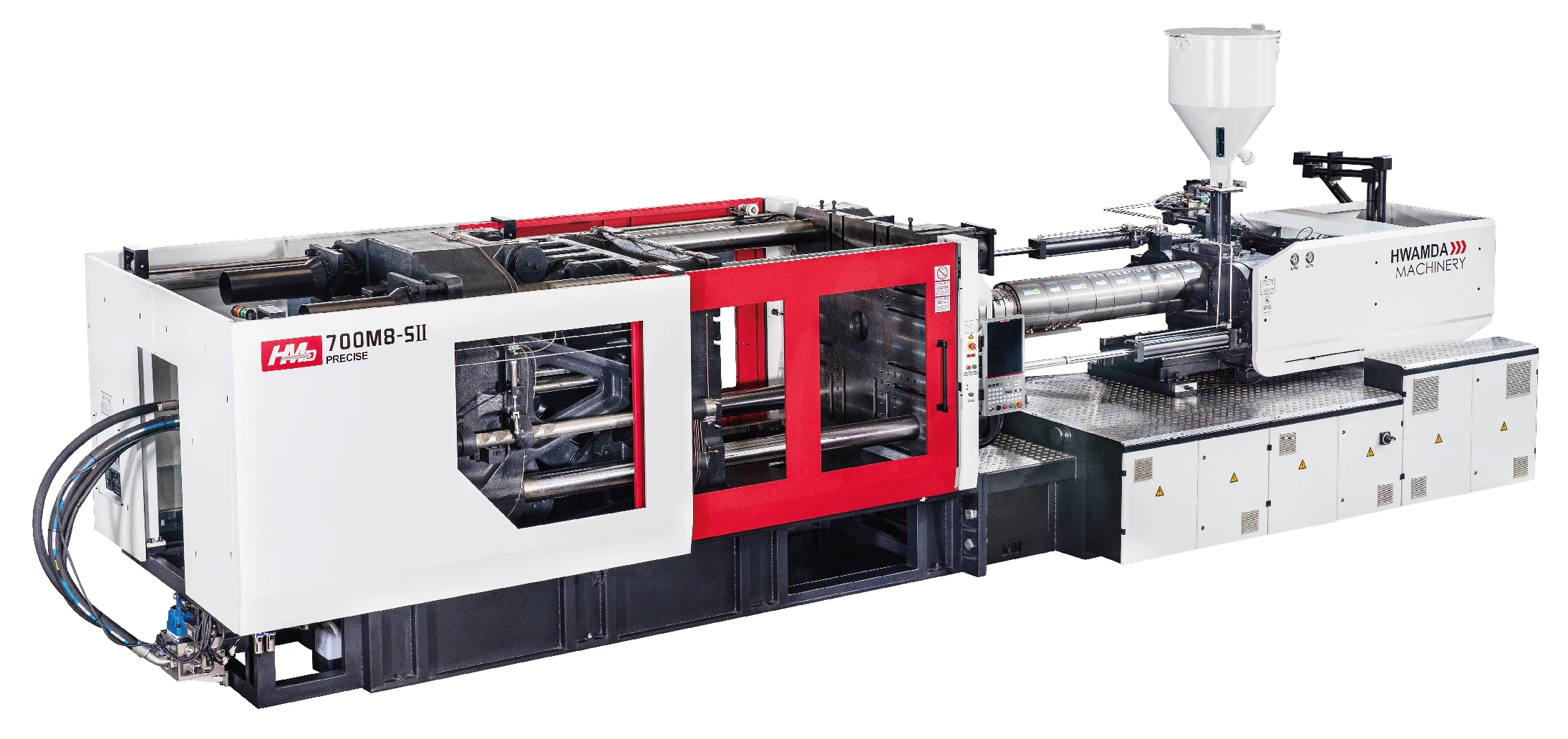
HMD M8SII SERIES
Review catalog configurations developed for paint bucket production, including three-axis robot take-out and in-mold labeling options. Final machine, mold and automation scope is confirmed from your product data.
CAPACITY & HANDLING
The supplied catalog lists normal three-axis robot take-out and IML as separate configuration groups. The capacity ranges are not interchangeable and remain subject to engineering review.
Catalog rows for normal part extraction after molding.
| Bucket capacity | Catalog model | Clamping reference | Injection weight | Mold thickness | Opening stroke | Tie-bar spacing | |
|---|---|---|---|---|---|---|---|
| 10L | HMD430M8-SII | 430 T | 1,646 g | 250–730 mm | 730 mm | 760×730 mm | Request review |
| 15L | HMD500M8-SII | 500 T | 1,858 g | 300–820 mm | 810 mm | 830×830 mm | Request review |
| 15–18L | HMD600M8-SII | 600 T | 2,324 g | 300–900 mm | 900 mm | 900×880 mm | Request review |
| 18–25L | HMD700M8-SII | 700 T | 2,903 g | 350–960 mm | 970 mm | 970×930 mm | Request review |
| 25–33L | HMD800M8-SII | 800 T | 3,225 g | 350–1000 mm | 1,040 mm | 1020×1000 mm | Request review |
Catalog rows where an IML configuration is listed.
| Bucket capacity | Catalog model | Clamping reference | Injection weight | Mold thickness | Opening stroke | Tie-bar spacing | |
|---|---|---|---|---|---|---|---|
| 10–15L | HMD500M8-SII | 500 T | 1,858 g | 300–820 mm | 810 mm | 830×830 mm | Request review |
| 15–18L | HMD600M8-SII | 600 T | 2,324 g | 300–900 mm | 900 mm | 900×880 mm | Request review |
| 18–22L | HMD700M8-SII | 700 T | 2,903 g | 350–960 mm | 970 mm | 970×930 mm | Request review |
| 25–33L | HMD800M8-SII | 800 T | 3,225 g | 350–1000 mm | 1,040 mm | 1020×1000 mm | Request review |
Catalog reference only. Product geometry, material, mold dimensions, automation and performance targets require engineering confirmation.
PRODUCT REQUIREMENTS
Capacity alone does not determine a machine. Share the product and mold information you already have; unknown values can be confirmed during the project review.
Overall dimensions, nesting features, handle areas and demolding details affect the mold and handling review.
Provide the resin grade and actual molded weights. Catalog PS shot weight is not the weight of a PP paint bucket.
Confirm normal robot take-out, in-mold labeling or an undecided decoration route before defining the automation interface.
Share mold dimensions, cavities, runner concept and the required stable output or cycle target.
CATALOG MODEL RANGE
Key machine and mold-interface values are reproduced as readable HTML from the supplied 2025.7 catalog. They are a selection reference, not a current project guarantee.
| Parameter | Unit | 430 | 500 | 600 | 700 | 800 |
|---|---|---|---|---|---|---|
| Injection volume(theoretical) | cm³ | 1,809 | 2,042 | 2,554 | 3,190 | 3,544 |
| Injection weight(PS) | g | 1,646 | 1,858 | 2,324 | 2,903 | 3,225 |
| Injection rate(PS) | g/s | 591 | 680 | 685 | 877 | 921 |
| Clamping force | kN | 4,300 | 5,000 | 6,000 | 7,000 | 8,000 |
| Mold opening stroke | mm | 730 | 810 | 900 | 970 | 1,040 |
| Dist. between tie bars (H×V) | mm | 760×730 | 830×830 | 900×880 | 970×930 | 1020×1000 |
| Mold thickness(Min–Max) | mm | 250–730 | 300–820 | 300–900 | 350–960 | 350–1000 |
| Machine dimension (L×W×H) | m | 8.0×2.0×2.6 | 8.3×2.1×2.6 | 9.9×2.3×2.5 | 10.4×2.4×2.7 | 11.5×2.5×3.3 |
Source: supplied catalog, version identified by filename as 2025.7. Confirm current configuration before ordering.
The complete catalog fields are grouped below. Original names, units and material basis are retained.
| Parameter | Unit | 430 | 500 | 600 | 700 | 800 |
|---|---|---|---|---|---|---|
| Injection volume(theoretical) | cm³ | 1,809 | 2,042 | 2,554 | 3,190 | 3,544 |
| Injection weight(PS) | g | 1,646 | 1,858 | 2,324 | 2,903 | 3,225 |
| Injection weight(PS) | oz | 58.1 | 65.6 | 82 | 102.4 | 113.8 |
| Injection rate(PS) | g/s | 591 | 680 | 685 | 877 | 921 |
| Screw diameter | mm | 80 | 85 | 85 | 95 | 95 |
| Injection pressure | MPa | 158 | 155 | 174 | 166 | 181 |
| Screw L/D ratio | — | 22.5:1 | 22.8:1 | 23.3:1 | 24:1 | 23:1 |
| Screw stroke | mm | 360 | 360 | 450 | 450 | 500 |
| Screw speed | r/min | 0–173 | 0–165 | 0–160 | 0–180 | 0–181 |
| Parameter | Unit | 430 | 500 | 600 | 700 | 800 |
|---|---|---|---|---|---|---|
| Clamping force | kN | 4,300 | 5,000 | 6,000 | 7,000 | 8,000 |
| Mold opening stroke | mm | 730 | 810 | 900 | 970 | 1,040 |
| Platen size | mm | 1032×1042 | 1128×1168 | 1210×1250 | 1325×1345 | 1420×1440 |
| Dist. between tie bars (H×V) | mm | 760×730 | 830×830 | 900×880 | 970×930 | 1020×1000 |
| Max. daylight | mm | 1,460 | 1,630 | 1,800 | 1,930 | 2,040 |
| Mold thickness(Min–Max) | mm | 250–730 | 300–820 | 300–900 | 350–960 | 350–1000 |
| Ejector stroke | mm | 185 | 210 | 240 | 265 | 280 |
| Ejection tonnage | kN | 111 | 111 | 151 | 182 | 182 |
| Parameter | Unit | 430 | 500 | 600 | 700 | 800 |
|---|---|---|---|---|---|---|
| Hydraulic system pressure | MPa | 17.5 | 17.5 | 17.5 | 17.5 | 17.5 |
| Pump motor power | kW | 72 | 48+31 | 60+31 | 60+60 | 72+60 |
| Heater power | kW | 47.8 | 51.6 | 56.2 | 61.6 | 61.4 |
| Number of temp control zones | — | 6 | 6 | 6 | 6 | 7 |
| Parameter | Unit | 430 | 500 | 600 | 700 | 800 |
|---|---|---|---|---|---|---|
| Oil tank | L | 500 | 590 | 550 | 680 | 1,000 |
| Machine dimension (L×W×H) | m | 8.0×2.0×2.6 | 8.3×2.1×2.6 | 9.9×2.3×2.5 | 10.4×2.4×2.7 | 11.5×2.5×3.3 |
| Machine weight | Ton | 18 | 22 | 25 | 32 | 38 |
APPLICATION-SPECIFIC ENGINEERING
The catalog identifies four design areas for this series. These descriptions do not replace project-specific performance validation.
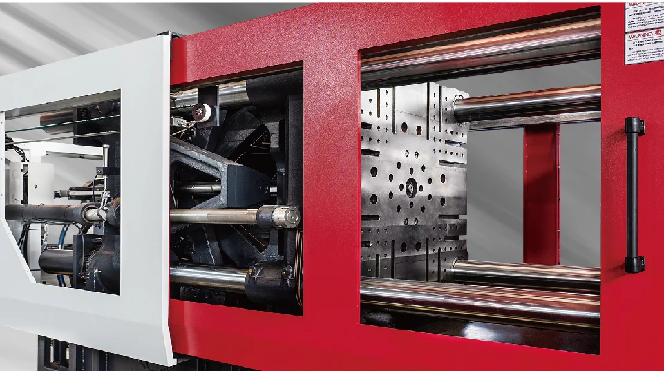
The platen structure is described for molds that place greater strength demand near the center. No fixed mold-life or load guarantee is inferred.
The catalog identifies a paint-bucket plasticizing and charging configuration. Charging performance is not presented as a guaranteed cycle or output.
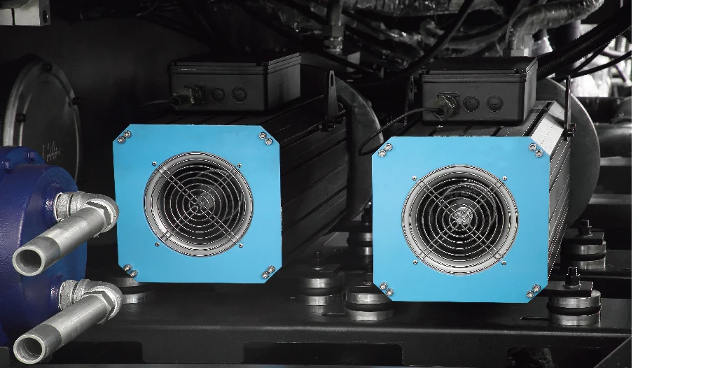
Opening and ejection coordination is listed for the series, except HMD430M8-SII. Final hydraulic and control scope requires confirmation.
Exception: HMD430M8-SII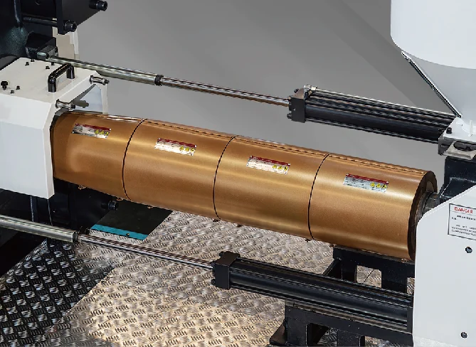
The catalog lists a 15+1 Φ12 quick-connect cooling-water manifold and infrared heating. No whole-machine energy-saving percentage is published here.
MACHINE–MOLD MATCHING
A catalog capacity row is only a starting point. Machine fit is reviewed from the actual mold, runner, product and automation interfaces.
Confirm loading clearance, mounting footprint and connection positions.
Check installation, part release, robot access and safe demolding space.
Use the complete runner and cavity shot, resin basis and recovery requirement—not bucket volume alone.
Review ejector stroke and force, cooling circuits, robot signals and IML interface requirements.
Engineering review sequence
HANDLING, IML & PROJECT SCOPE
A listed handling mode does not mean every robot, mold, label system or auxiliary is included in the bare-machine price.
Machine configuration for the confirmed model
Robot interface and extraction requirement
Part release, placement and downstream handling
Machine and mold interface for IML
Label, robot and control requirements
Placement, inspection and stacking scope
Paint bucket and lid mold
Robot or IML equipment
Cooling and material handling
Installation, trial and acceptance boundary
SOURCE & EVIDENCE
The model tables and feature descriptions are based on the supplied catalog. Current availability, configuration and commercial scope still require product and engineering confirmation.
An approved series-specific running video has not yet been supplied. Add real molding and take-out or IML footage before public launch.
PROJECT CONFIGURATION & PRICE
Send the bucket capacity, handling method and the product or mold information you already have. Missing engineering details will not block the enquiry.
Bucket and lid drawing or sample
Material and actual molded weight
Take-out, IML or not sure
Existing mold data and target output
BUYER QUESTIONS
The catalog lists five normal three-axis take-out rows from 10 L to 25–33 L and four IML rows from 10–15 L to 25–33 L. Each row remains a catalog reference pending product, mold and engineering review.
They are separate groups. For example, HMD700M8-SII is listed for 18–25 L with normal take-out and 18–22 L with IML, so one range must not be copied to the other.
No IML row for HMD430M8-SII appears in the supplied catalog. This means “not listed in this catalog,” not an absolute statement that the configuration is impossible.
It is the catalog shot-weight reference based on PS. It is not the actual weight of a PP paint bucket and should not be used as a direct material conversion.
It can be reviewed after checking mold dimensions, thickness, runner and shot requirement, platen and tie-bar fit, opening, ejector, cooling and automation interfaces.
Only the specific quotation defines what is included. Machine, mold, robot or IML equipment, auxiliaries, trial and service scope must be confirmed separately.
The supplied catalog does not provide a tested product–mold–automation combination. Stable cycle and output require confirmation from the actual product, material, mold, cooling and handling conditions.