 HWAMDA
Standard cup production
Focus on filling, cooling, cup release and the required collection method.
- 01Mold the cup
- 02Take out
- 03Place / collect
CUP FIRST. PRODUCTION CELL NEXT.
High-speed injection molding for thin-wall cups, configured around your cup design, mold, machine, automation, cooling and production target.
01 / START WITH THE PRODUCT
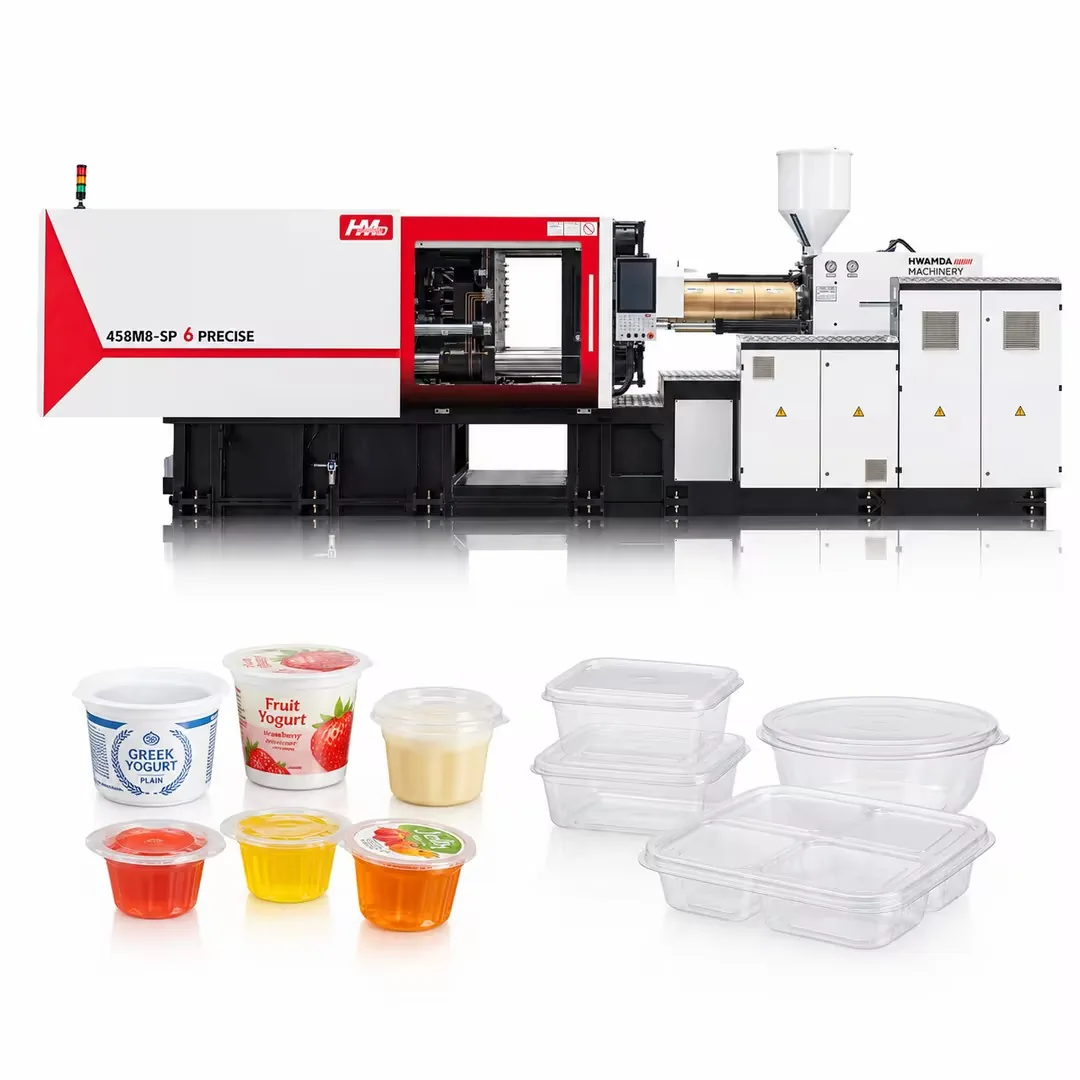
For injection molded plastic cups, the rim, body and base matter as much as nominal volume. Send the actual product you want to make.
Review the cup profile, rim and sealing or lid interface.
Review the base, wall transitions and release requirements.
Share a photo or drawing. We will review its suitability for injection molding and work backward to the production cell.
Send your cup specification02 / FILLING & RESPONSE
Not every cup needs a high-speed machine. Thin wall cup injection molding becomes more demanding as wall thickness decreases, flow paths lengthen, or cavity and output requirements increase.
High speed cup injection molding is a system task—not simply a higher injection-speed number.
03 / DEFINE THE BRIEF
Start with the product, not a machine tonnage. Your target output is a design input to evaluate alongside the cup and mold.
04 / MACHINE SELECTION
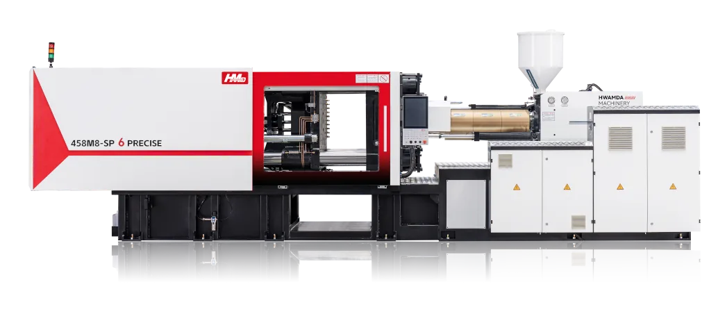
A plastic injection molding machine for cup production must provide the required filling capability while accommodating the mold and its handling interfaces.
05 / MACHINE–MOLD MATCHING
The cup design, mold and machine should be reviewed together. Mold supply and matching start with the product drawing and the intended production route.
Cup geometry, rim, lid fit and wall transitions.
Cavity layout, runner / gating, filling balance, venting and cooling.
Ejection method, robot access and IML compatibility where required.
06 / CAVITIES & OUTPUT
Compare cavity concepts against your output target and available production time. Each change affects the equipment around the mold.
07 / RECORDED CUP PRODUCTION
Cups recorded in production with their cavity count, cycle time and calculated hourly output. Your cycle depends on the cup, resin, mold and cooling, so we confirm it for your project.
| Cup type | Cavities | Cycle time | Output/hour (calculated) |
|---|---|---|---|
| PS airline cup | 24 | 5.9 s | 14,600 |
| PS tea cup | 16 | 7.0 s | 8,200 |
| Crystal cup | 12 | 8.0 s | 5,400 |
Output per hour = cavities × 3,600 ÷ cycle time, before planned stops and quality checks.
plastic cup moldhigh-speed injection molding machine08 / INJECTION OR THERMOFORMING
Both processes are used to make plastic cups. The cup design, wall section, rim, decoration and output decide which route fits.
| Aspect | Injection molding | Thermoforming |
|---|---|---|
| Raw material | Plastic pellets, melted in the machine | Extruded plastic sheet, heated before forming |
| How the cup is formed | Melt is injected into closed mold cavities | Heated sheet is formed in the mold, then cut from the sheet |
| Wall, base and rim | Shaped by the mold on both sides | Wall follows the sheet as it stretches; rims may be rolled in a separate step |
| Decoration | In-mold labeling (IML) during molding, or printing afterwards | Printing after forming, or pre-printed sheet |
| Trim material | Runner material when a cold runner is used | Sheet skeleton left after cutting |
Send your cup sample or drawing and we will review whether injection molding suits it.
Send Your Cup Sample or Drawing09 / CHOOSE THE PRODUCTION ROUTE
Decide on the finish before fixing the mold and automation concept.
Focus on filling, cooling, cup release and the required collection method.
Add coordinated label handling and placement. Review the label, mold interface, take-out and machine sequence together.
10 / PART HANDLING
Confirm how the cup releases, clears the mold and reaches the next handling step. Review sprue handling when applicable and the required placement or conveyor interface.
Conceptual sequence: mold closing is enabled only after the robot is clear and the required safety interlocks are satisfied. Final motion timing depends on the selected cell.
11 / COOLING
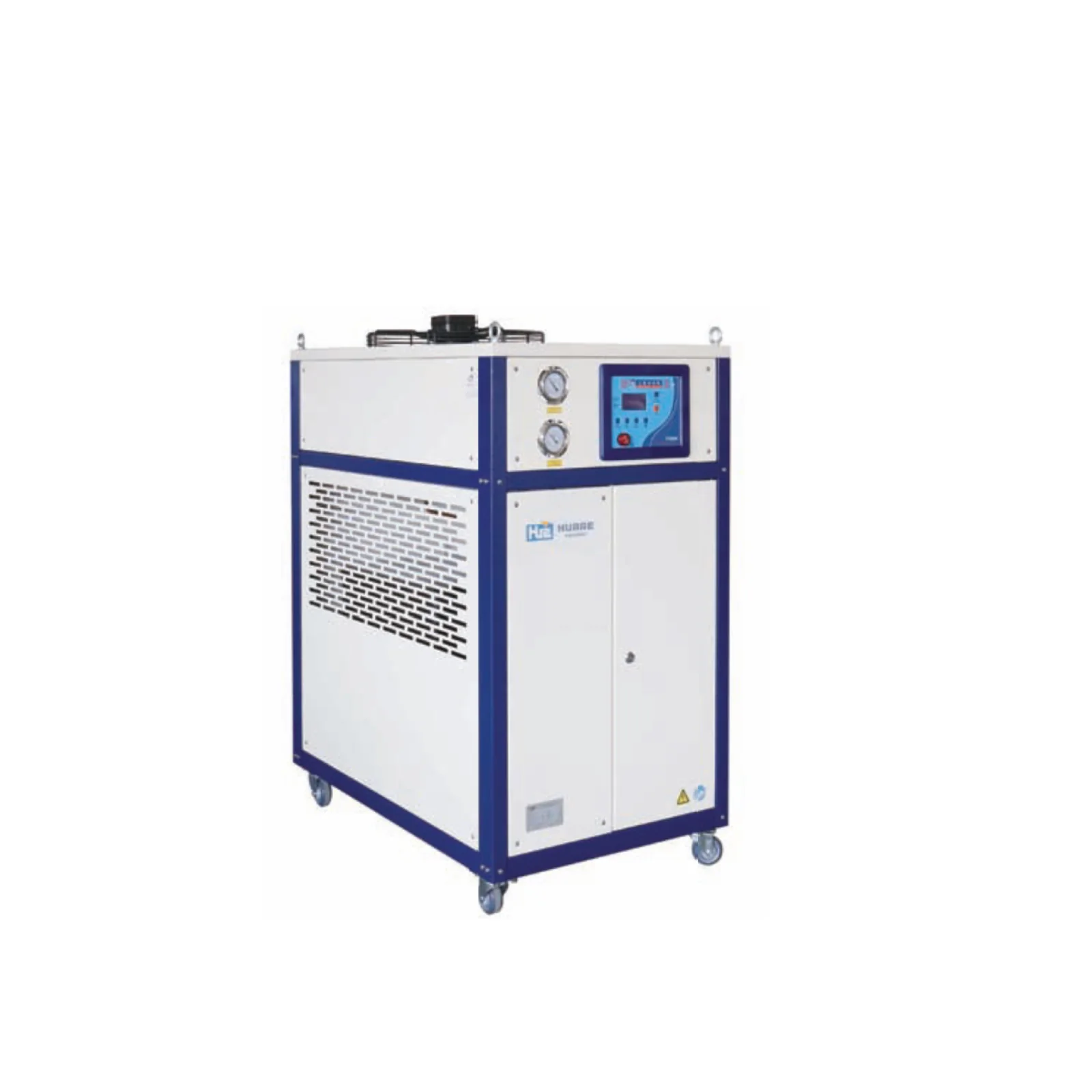
Machine speed alone cannot resolve a cooling bottleneck. Review mold heat load and cooling circuits against part release, dimensional stability and cycle consistency.
The required water conditions, plant supply and resin determine the cooling configuration. A chiller and a mold temperature controller perform different functions; neither combination nor sizing is assumed from cup volume alone.
Explore cooling and auxiliary equipment12 / MATERIAL HANDLING
Drying depends on the resin grade and its moisture condition. Confirm the material requirements before selecting a dryer or feeding arrangement.
Review the hopper and loader around one machine’s material consumption and supply arrangement.
Review centralized conveying separately, including material routing, machine count and plant layout.
13 / THE COMPLETE PRODUCTION CELL
HWAMDA can configure machine selection, mold matching, automation and auxiliary requirements around your cup product and production target.
Injection molding machine + cup moldConceptual equipment relationship. Cooling is a support loop—not a stage through which the cups travel.
14 / YOUR STARTING POINT
Send the product drawing, resin and production target. Develop the mold concept, then coordinate machine capability, cooling, automation and feeding.
Plan a new cup production cellSend mold dimensions, weight, cavities, product details and injection requirements if known. Include the existing machine and output target.
Beyond physical fit, review filling, cooling, ejection and take-out interfaces.
Check Your Existing Cup Mold With a HWAMDA High-Speed Machine15 / CUP PROJECT REVIEW
Agree on the cup acceptance requirements and review the selected machine–mold–handling configuration.
Confirm the trial conditions, molded-cup result, machine and mold configuration, and handling sequence against the agreed project brief.
16 / BUYER QUESTIONS
Start with the cup material, dimensions, weight, wall section, cavity concept and target output. Review injection capability, projected area, mold space and take-out access together to select a plastic cup injection molding machine.
Thin walls, longer flow paths, multiple cavities and demanding output targets can make filling and machine response more critical. Not every cup requires a high-speed machine; the cup and mold define the requirement.
Wall thickness and flow length affect filling requirements. Cavity count affects the total shot, projected area, mold size, cooling load and handling demand. Evaluate these together, not as independent maximum values.
Compare cavity concepts against your required output, available production time, cup geometry and machine–mold limits. More cavities are not automatically better: filling balance, cooling, release and handling must remain workable.
Send the mold dimensions, weight, cavity count, product drawing and existing machine information. The review covers mounting and mold space as well as injection capability, cooling, ejection and automation interfaces.
IML can be considered where the cup design and label requirements support it. The mold, label handling, placement accuracy, take-out and machine sequence need to be coordinated as one production route.
Selection depends on mold heat load, resin, operating conditions and the plant cooling-water supply. A chiller and a mold temperature controller have different roles; the project review determines which equipment is appropriate.
Start with a cup photo or drawing, material and required output. Dimensions, weight, wall section, cavity preference, existing mold or machine details and IML requirements help define the configuration. You do not need to select a machine tonnage first.
Not always. A plastic cup making machine often means a thermoforming machine that forms cups from plastic sheet. An injection molding machine molds cups from plastic pellets in a closed mold. This page covers the injection molding route; send your cup to check which route suits it.
It depends on cavities and cycle time. Recorded examples on this page: a 24-cavity PS airline cup at 5.9 s gives about 14,600 cups per hour, and a 12-cavity crystal cup at 8.0 s gives 5,400 per hour (calculated, before planned stops). Your output is confirmed from your cup, mold and machine.
HWAMDA can coordinate machine selection, mold supply and matching, automation and auxiliary requirements around your cup project. The proposal defines the selected equipment, interfaces, supply scope and acceptance requirements.
17 / YOUR CUP PROJECT
Tell us which cup you want to produce. A photo or drawing is a useful starting point; add engineering details if you have them.
No machine tonnage selection required.
Producing containers rather than cups? ↗