 HWAMDA
Direct mold-area review
Tie-bar spacing, platen dimensions, mold thickness and opening requirements can be evaluated as one mold-envelope decision.

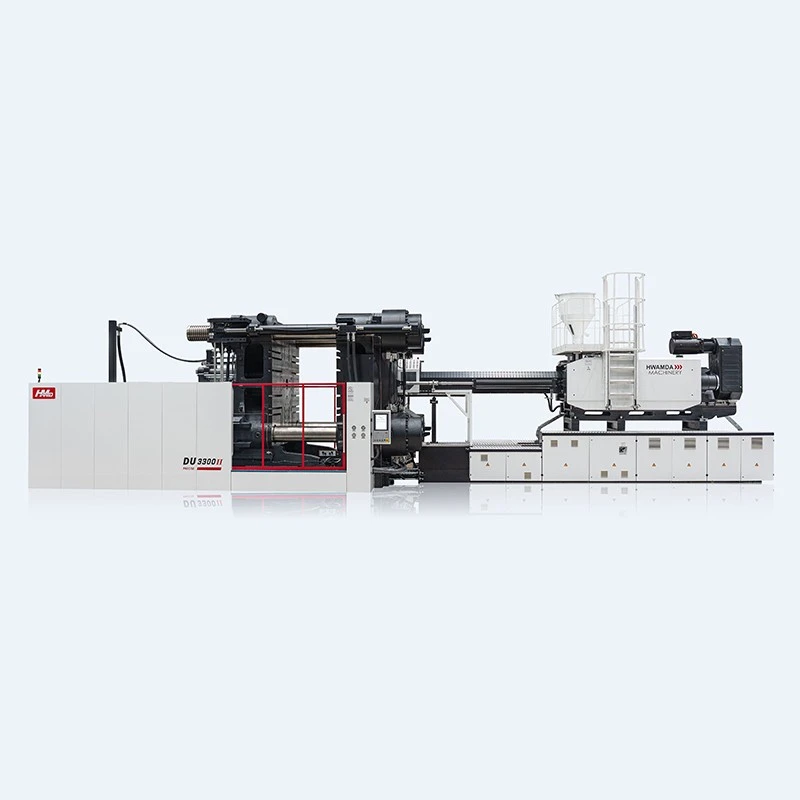
DU SERIES · TWO-PLATEN PLATFORM
Compare the current DU II range by clamping force, mold space and injection-unit options, then send your part and mold data for an engineering configuration review.
STRUCTURAL CHOICE
A two-platen machine places the mold between the fixed and moving platens and develops high-pressure clamping through the tie-bar locking system. The right choice still depends on the mold, opening requirement and complete production task.
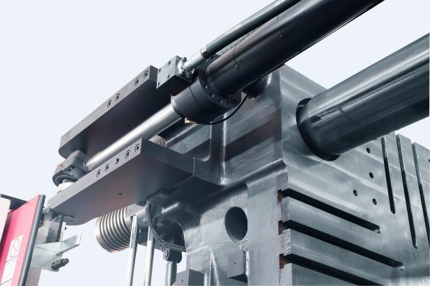
Tie-bar spacing, platen dimensions, mold thickness and opening requirements can be evaluated as one mold-envelope decision.
The DU platform uses a two-platen clamping layout rather than a rear toggle linkage. Final configuration is reviewed against the required mold movement and load.
Clamping force alone is not enough. Injection demand, mold interface, ejection and plant layout remain part of the same engineering review.
SELECTION CONTEXT
Neither architecture is universally better. Use the mold envelope, opening task, injection demand and production priorities to decide which platform deserves an engineering review.
| Selection factor | Two-platen | Three-platen / toggle |
|---|---|---|
| Clamping structure | Two main platens with tie-bar locking and hydraulic clamp movement. | Fixed, moving and rear support platens with a toggle linkage. |
| Mold-space review | Often considered when a large mold envelope or long opening task drives the machine selection. | Often considered where the mold fits a conventional toggle machine envelope. |
| Machine selection | Review platen, tie-bar, thickness, opening and injection unit together. | Review the same project inputs against the toggle machine specification. |
| Best next step | Submit the actual mold drawing for a DU configuration check. | Compare against the verified three-platen series after the same mold review. |
CURRENT DU II RANGE
The first comparison keeps the decision focused on clamping and mold-space values transcribed from the current technical sheets. Injection-unit options are compared separately below.
| Model | Clamping force | Platen size (H × V) | Tie-bar spacing (H × V) | Mold thickness | Max. daylight | Machine dimensions (L × W × H) | Action |
|---|---|---|---|---|---|---|---|
| DU650II | 6,500 kN | 1420 × 1370 mm | 1060 × 930 mm | 400–950 mm | 1,750 mm | 7.9 × 2.7 × 2.7 m | Discuss model |
| DU750II | 7,500 kN | 1540 × 1440 mm | 1140 × 960 mm | 450–950 mm | 1,850 mm | 8.1 × 2.9 × 2.7 m | Discuss model |
| DU900II | 9,000 kN | 1560 × 1540 mm | 1180 × 1020 mm | 500–1100 mm | 2,100 mm | 9.2 × 3.1 × 3.7 m | Discuss model |
| DU1200II | 12,000 kN | 1870 × 1760 mm | 1320 × 1200 mm | 600–1250 mm | 2,650 mm | 10.2 × 3.4 × 3.8 m | Discuss model |
| DU1600II | 16,000 kN | 2200 × 2080 mm | 1560 × 1450 mm | 700–1550 mm | 3,250 mm | 12.2 × 3.8 × 4.2 m | Discuss model |
| DU2400II | 24,000 kN | 2545 × 2335 mm | 1850 × 1620 mm | 800–1700 mm | 3,800 mm | 14.1–15.4 × 4.4 × 4.2–4.4 · by injection unit m | Discuss model |
Source: current DU technical specification and platen-dimension sheets. The source presents mold-opening values in paired notation; confirm the exact movement definition during engineering review.
ENGINEERING SELECTION
The six-model range is a starting point. A useful recommendation comes from the actual product, material, mold envelope, movement and injection requirement.
INJECTION SELECTION
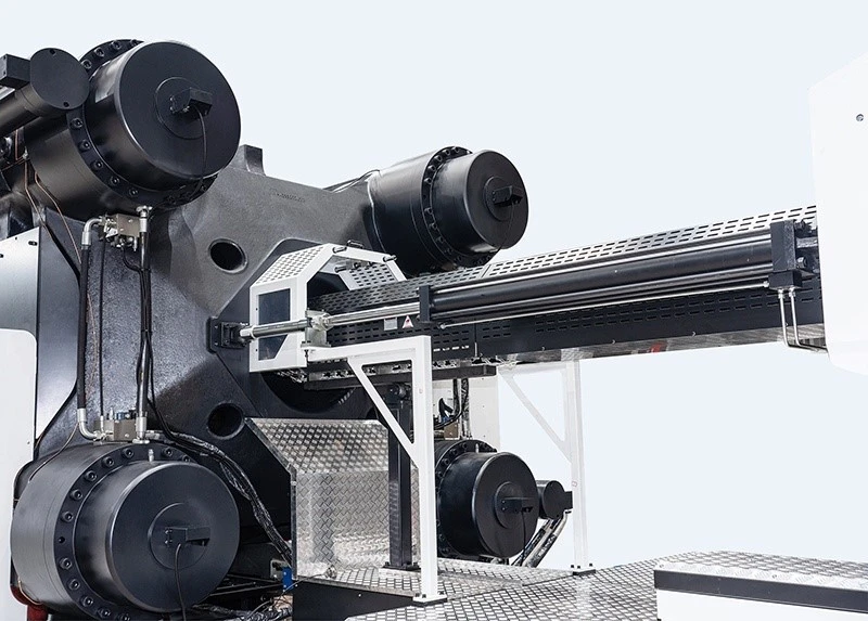
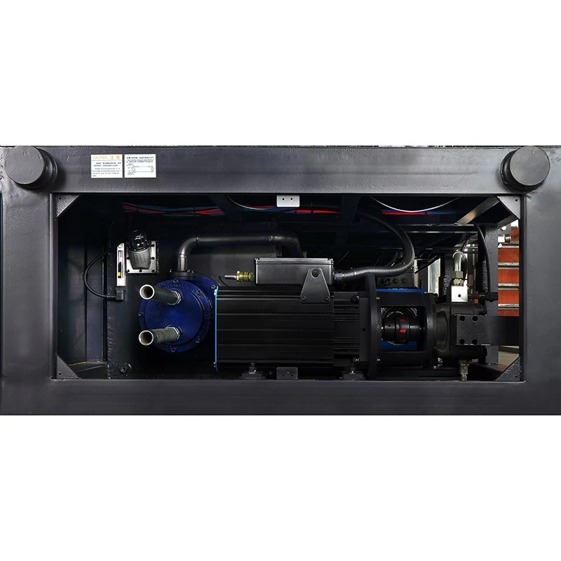
Each row keeps screw diameter, theoretical volume, PS reference weight, injection rate and pressure together. Do not compare a maximum weight from one option with pressure from another.
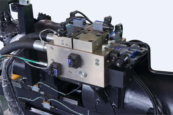
| Option | Screw Ø | Theoretical volume | Injection weight (PS) | Injection rate | Injection pressure |
|---|---|---|---|---|---|
| A | 85 mm | 2,554 cm³ | 2,324 g | 627 g/s | 208 MPa |
| B | 90 mm | 2,863 cm³ | 2,605 g | 702 g/s | 185 MPa |
| C | 95 mm | 3,190 cm³ | 2,903 g | 783 g/s | 166 MPa |
| D | 105 mm | 3,896 cm³ | 3,546 g | 956 g/s | 136 MPa |
| Option | Screw Ø | Theoretical volume | Injection weight (PS) | Injection rate | Injection pressure |
|---|---|---|---|---|---|
| A | 85 mm | 2,554 cm³ | 2,324 g | 627 g/s | 208 MPa |
| B | 90 mm | 2,863 cm³ | 2,605 g | 702 g/s | 185 MPa |
| C | 95 mm | 3,190 cm³ | 2,903 g | 783 g/s | 166 MPa |
| D | 105 mm | 3,896 cm³ | 3,546 g | 956 g/s | 136 MPa |
| Option | Screw Ø | Theoretical volume | Injection weight (PS) | Injection rate | Injection pressure |
|---|---|---|---|---|---|
| A | 90 mm | 3,308 cm³ | 3,010 g | 646 g/s | 235 MPa |
| B | 100 mm | 4,084 cm³ | 3,717 g | 798 g/s | 190 MPa |
| C | 110 mm | 4,942 cm³ | 4,497 g | 965 g/s | 157 MPa |
| D | 120 mm | 5,881 cm³ | 5,352 g | 1,149 g/s | 132 MPa |
| Option | Screw Ø | Theoretical volume | Injection weight (PS) | Injection rate | Injection pressure |
|---|---|---|---|---|---|
| A | 105 mm | 5,022 cm³ | 4,570 g | 886 g/s | 217 MPa |
| B | 115 mm | 6,024 cm³ | 5,482 g | 1,063 g/s | 181 MPa |
| C | 125 mm | 7,118 cm³ | 6,477 g | 1,256 g/s | 153 MPa |
| D | 135 mm | 8,302 cm³ | 7,555 g | 1,465 g/s | 132 MPa |
| Option | Screw Ø | Theoretical volume | Injection weight (PS) | Injection rate | Injection pressure |
|---|---|---|---|---|---|
| A | 130 mm | 9,291 cm³ | 8,455 g | 1,255 g/s | 207 MPa |
| B | 140 mm | 10,776 cm³ | 9,806 g | 1,455 g/s | 179 MPa |
| C | 150 mm | 12,370 cm³ | 11,257 g | 1,670 g/s | 156 MPa |
| D | 160 mm | 14,074 cm³ | 12,808 g | 1,901 g/s | 137 MPa |
| International size rating | Option | Screw Ø | Theoretical volume | Injection weight (PS) | Injection rate | Injection pressure |
|---|---|---|---|---|---|---|
| 32000 / 2400 | A | 160 mm | 20,106 cm³ | 18,297 g | 1,849 g/s | 158 MPa |
| 32000 / 2400 | B | 170 mm | 22,687 cm³ | 20,645 g | 2,087 g/s | 140 MPa |
| 40000 / 2400 | A | 180 mm | 25,444 cm³ | 23,145 g | 1,877 g/s | 156 MPa |
| 40000 / 2400 | B | 190 mm | 28,339 cm³ | 25,788 g | 2,091 g/s | 140 MPa |
| 58000 / 2400 | A | 200 mm | 37,680 cm³ | 34,289 g | 2,167 g/s | 154 MPa |
| 58000 / 2400 | B | 210 mm | 41,542 cm³ | 37,803 g | 2,390 g/s | 140 MPa |
MOLD VALIDATION
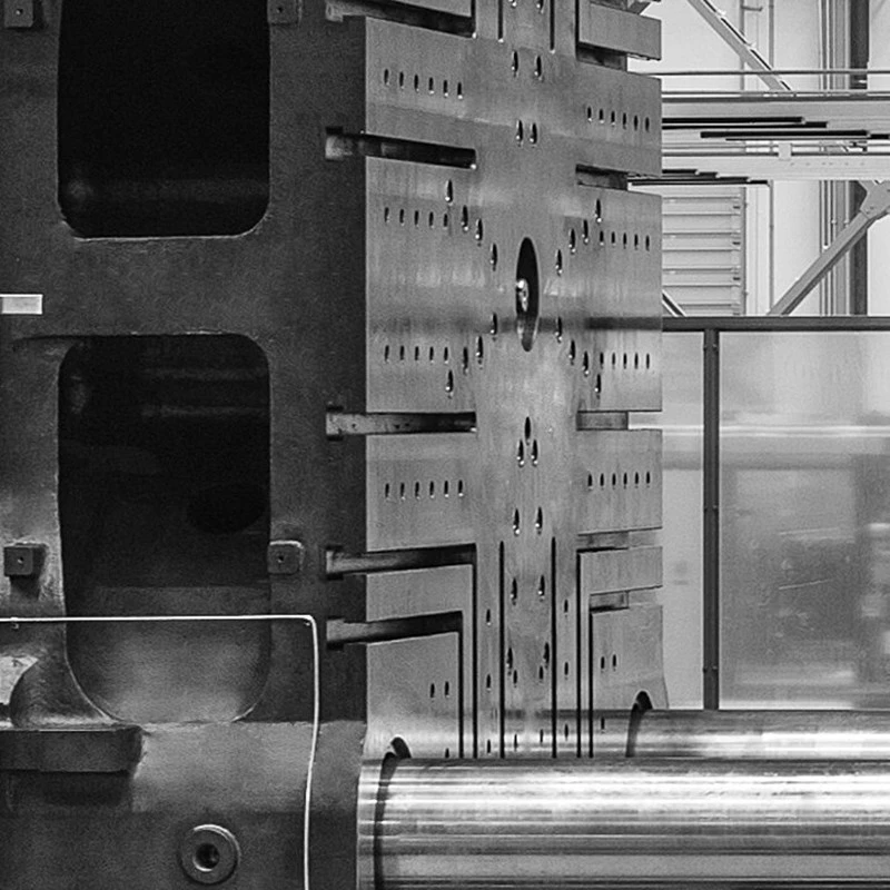
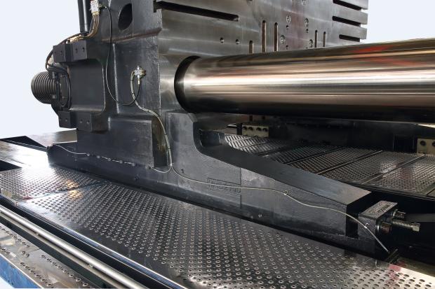
Catalog values support a preliminary review only. Final machine–mold compatibility requires engineering confirmation using the actual mold drawing and interface data.
Overall mold dimensions and thickness
Mold weight and lifting requirement
Tie-bar and platen interface
Opening and ejection requirement
Core pulling or special movements
Shot, runner and material requirement
APPLICATIONS & PROOF
The current project files verify the DU model range and technical drawings. Current DU II application photography and running footage are still required before this development page is released.
Use the actual mold size, thickness, opening path and projected area to assess the platform.
Interface data, ejector, actions, connections and sample requirements must be checked before compatibility is confirmed.
Part, resin, mold and production requirements are reviewed together before the model and injection unit are quoted.
DU PROJECT BRIEF
Start with your part and mold information. Final pricing depends on the DU model, injection unit, selected configuration, mold interface, automation, auxiliaries and service scope.
Three required fields to start
Optional engineering details can be added
Part or mold files can be attached
Unknown values can be reviewed after enquiry
BUYER QUESTIONS
It is an injection molding machine whose clamping area is formed by a fixed platen and a moving platen, with clamping force developed through the tie-bar locking and hydraulic clamp system.
The principal difference is the clamping architecture. A two-platen machine does not use the rear support platen and toggle linkage found in a conventional three-platen toggle machine. The best choice depends on the actual mold and production task.
Start with the part, material, projected area, mold dimensions and thickness, opening and ejection requirements, injection demand and production target. HWAMDA can then review the suitable model and injection unit.
Send the mold drawing and interface data. Tie-bar spacing, platen size, mold thickness, opening, ejection, actions, weight and injection requirement must be checked together.
It is the catalog reference shot weight calculated for polystyrene. Actual available shot weight depends on the selected material and should be confirmed for the project.
Yes, the current technical sheets show multiple injection-unit and screw options. Each option must be evaluated as a complete set of volume, PS weight, rate and pressure values.
The selected DU model, injection unit, options, mold and interface requirements, automation or auxiliaries, logistics and agreed service scope determine the final quotation.