M8SII Series

Servo Hydraulic Injection Molding Machines

The M8SII general-purpose series brings together rigid clamping, optimized injection and digital closed-loop servo-hydraulic control. Match the machine, injection unit and mold to your production requirements.

Current catalog range25 models
Clamping force900–33,000 kN
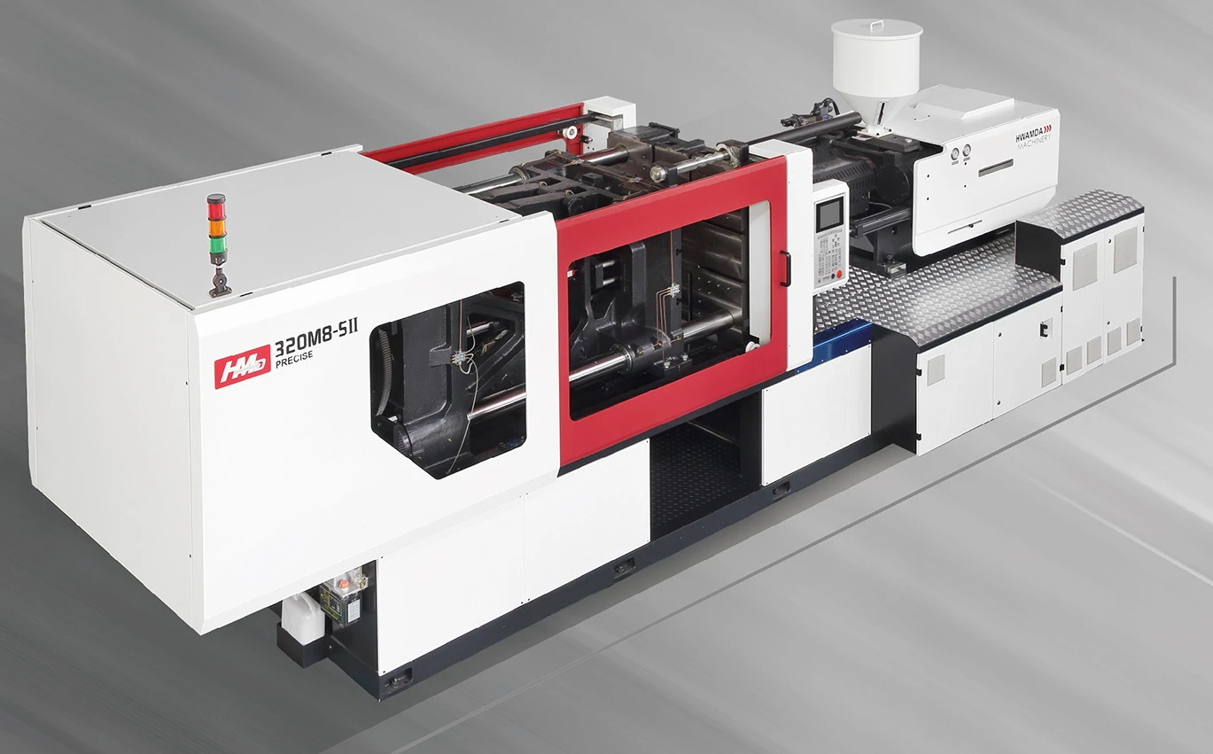
HWAMDA HMD320M8-SII servo hydraulic injection molding machine, three-quarter view
HMD320M8-SII servo hydraulic injection molding machine

UNDERSTAND THE ARCHITECTURE

Why choose a servo hydraulic injection molding machine?

M8SII uses a servo motor and drive with hydraulics—not an all-electric architecture. The meaningful comparison is how the complete system supports your process.

  1. 01Controller

    Process commands

  2. 02Servo drive & motor

    Controlled drive response

  3. 03Hydraulic system

    Pressure and flow

  4. 04Machine motion

    Clamping and injection

Response

Review how the control, drive and hydraulics work together during the molding cycle.

Process stability

Match pressure control and low-flow behavior to the part and mold requirement.

Energy use

Evaluate energy consumption with the actual material, cycle and operating conditions.

FOUR CORE SYSTEMS

Look inside the M8SII platform

Review the mechanical structure, injection assembly, servo-hydraulics and operator controls as one machine. These details establish the basis for your configuration.

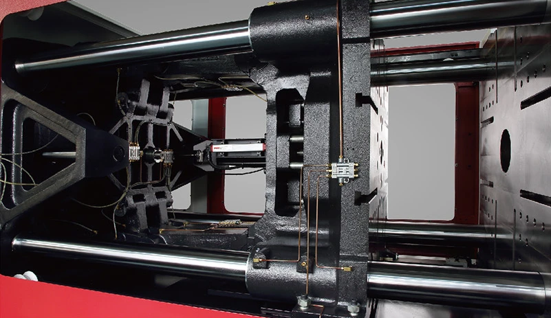
M8SII clamping assembly showing the platen, tie bars and toggle mechanism
01 / ENGINEERING

Clamping unit

  • High-rigidity, reinforced platen structure
  • Finite-element optimization
  • T-slot mounting and automatic mold adjustment

Start with a stable mold interface and check the opening and ejection space your mold needs.

Engineering details

The clamping structure uses a strengthened central section and tie-bar design, with finite-element optimization. Smooth movement and tie-bar durability are design priorities. T-slot mounting and hydraulic-motor-driven automatic mold adjustment support mold installation.

Send Your Mold Dimensions
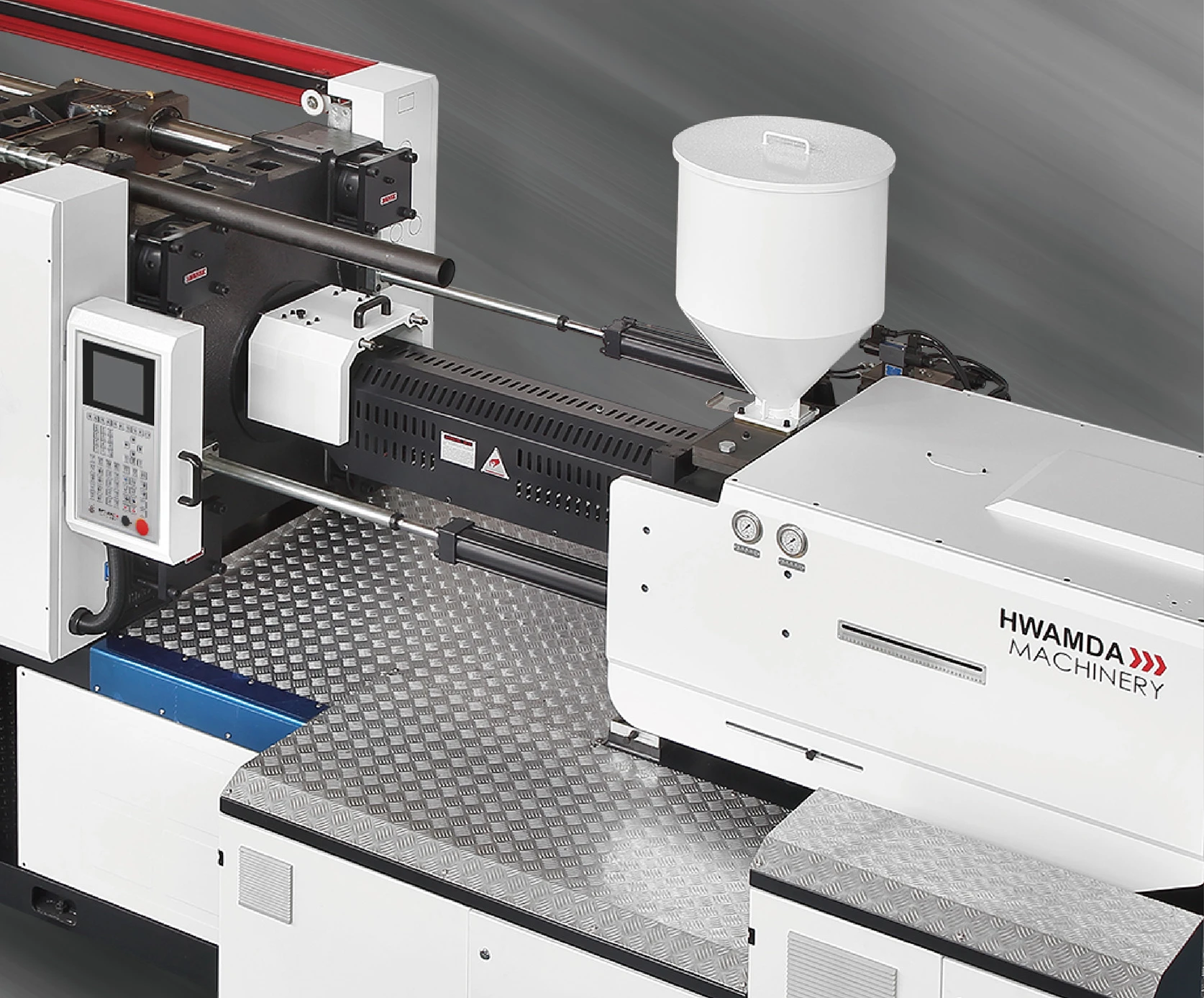
M8SII injection-side assembly with barrel, hopper and carriage
02 / ENGINEERING

Injection unit

  • Optimized screw and barrel
  • Double-cylinder injection and double carriage cylinder
  • Guide-liner design for low-resistance movement

Choose a complete injection option around the resin, shot requirement and pressure needed.

Engineering details

The screw and barrel are optimized for plasticizing performance. Double-cylinder injection, double carriage cylinders and the guide-liner design support smooth movement. Key injection structural components are reinforced. Compare the screw diameter, shot volume, PS weight, rate and pressure within one option—not across different columns.

Compare Injection Options
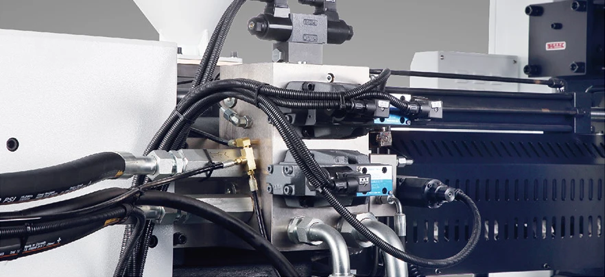
Hydraulic connections and valve assembly shown in the current M8SII catalog
03 / ENGINEERING

Servo-hydraulic system

  • Synchronous servo motor and drive
  • Digital closed-loop control
  • Response, pressure control and low-flow stability

Evaluate energy use and process control against your actual production cycle.

Engineering details

A synchronous servo motor and drive work with the hydraulic system under digital closed-loop control. The design focuses on fast response, pressure control and stable operation at low flow. For an energy-saving injection molding machine project, assess the complete cycle and operating conditions; a catalog motor rating is not a measured energy-consumption result.

Discuss Your Process Requirements
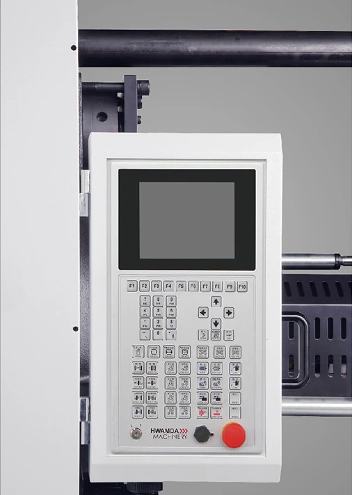
M8SII operator control panel with LCD display and physical controls
04 / ENGINEERING

Electric & control unit

  • High-performance controller with large LCD
  • Straightforward operator interface
  • Safety relay, hydraulic safety valve and protective design

Review the operator interface, safety requirements and electrical configuration together.

Engineering details

The control system combines a large LCD interface with physical operating controls. Catalog safety provisions include a safety relay, hydraulic safety valve and protective guarding. Controller version, electrical components and destination-specific requirements belong in the agreed machine configuration.

Confirm Electrical & Control Requirements

M8SII MODELS & SPECIFICATIONS

Find your starting point

Choose a clamping-force range and model to review mold space, matched injection options and complete specifications.

Selected model: HMD90M8-SII

HMD90M8-SII

Request a Quote
Clamping force
900 kN
Tie-bar spacing (H × V)
360 × 360 mm
Mold thickness (min–max)
150–360 mm
Full specificationsClamping, injection options & dimensions

Injection weight and rate reference PS. Each table row is a matched injection option. Swipe tables horizontally on mobile to view all fields.

Clamping, mold space & hydraulics

Clamping force
900 kN
Mold opening stroke
320 mm
Platen size
535 × 535 mm
Tie-bar spacing (H × V)
360 × 360 mm
Max. daylight
680 mm
Mold thickness (min–max)
150–360 mm
Ejector stroke
100 mm
Ejector force
31 kN
Hydraulic system pressure
16 MPa
Oil tank
125 L

Injection unit · 282/90

International size rating. Each row below is one complete source-listed option.

OptionScrew Ø (mm)Volume (cm³)Weight, PS (g)Rate, PS (g/s)Pressure (MPa)Screw L/D
A321291179821922:1
B3616314812317319.6:1
C4020118315214017.6:1
Screw stroke
160 mm
Screw speed
0–300 r/min
Pump motor power
18.7 kW
Heater power
8.6 kW
Temperature-control zones
4
Machine weight
3.5 Ton
Machine dimensions (L × W × H)
4.0 × 1.2 × 1.9 m

M8SII catalog, October 2025 · printed pages 1314. Values support preliminary review; confirm the final machine configuration and installation drawing for your project.

HOW TO SELECT THE RIGHT M8SII

Start with the part. Validate the whole configuration.

A model number is a starting point, not a complete machine recommendation. Follow the part, mold and process requirements through the selection.

  1. 01

    Define the part

    Share the product drawing or sample, material grade, part weight and cavity count.

  2. 02

    Check the mold

    Review dimensions, thickness, weight, required opening, ejection and any core-pulling motions.

  3. 03

    Match the injection unit

    Check shot volume, PS-reference weight, pressure and plasticizing requirements together.

  4. 04

    Define the production cell

    Agree target output, automation, auxiliaries, plant utilities and the service scope.

Send Part & Mold Data for Machine Selection

MOLD COMPATIBILITY

Check the mounting and movement—not only the tonnage

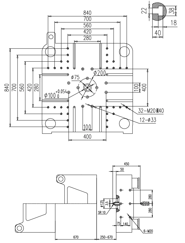
Use the model’s platen, tie-bar and mold-thickness values for preliminary review. Final fit also depends on the mounting and movement interfaces shown in your actual mold drawing.

HMD320M8-SII platen and side-view mold-space dimension drawings
HMD320M8-SII platen dimensions & mold space

Mold dimensions, thickness and weight

Platen layout, tie-bar clearance and mounting

Required mold opening and part removal space

Ejector position, stroke and force

Core-pulling and other special motions

Nozzle, shot and injection-pressure requirements

Send Your Mold Drawing

APPLICATIONS & PROCESS EVIDENCE

Connect the machine to your actual part

A useful application record identifies the machine, injection option, mold, resin and part. Your project discussion can begin with a sample or drawing.

PROJECT-SPECIFIC VALIDATIONReview the M8SII configuration with your molded part

Connect the selected model and injection unit to the resin, mold, part and agreed trial conditions. Cycle and output are confirmed only against the corresponding project record.

Looking for a dedicated process? Review PET preform machines, high-speed thin-wall machines, paint-bucket configurations or the DU two-platen series.

HWAMDA MANUFACTURING

Engineering, assembly and inspection behind the machine

From product development and material inspection to assembly and delivery checks, review how HWAMDA prepares your machine for production.

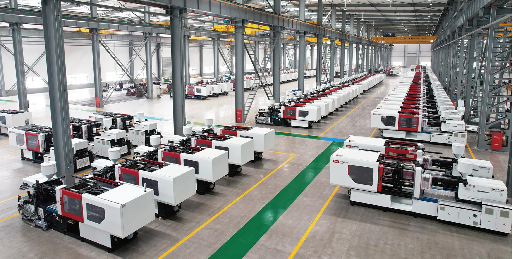
Rows of red and white HWAMDA machines on the factory assembly floor
HWAMDA production & assembly
01

R&D & configuration

Mechanical, electrical and hydraulic development supports machine configuration and project review.

02

Material inspection

Material checks cover composition, microstructure, hardness, surface finish and dimensions.

03

Assembly process control

Hydraulic, clamping, injection and electrical installation checks are part of assembly control.

04

Delivery inspection

Machine appearance, safety functions, performance and accompanying parts are checked before delivery.

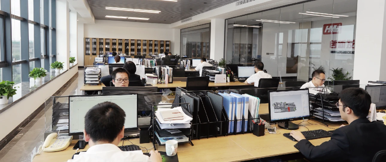
HWAMDA engineering team working at design workstations
Product development
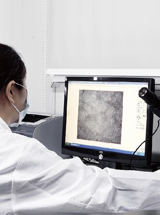
HWAMDA technician reviewing a material microstructure image
Material inspection

SERVICE & PROJECT SUPPORT

Plan the support alongside the machine

Discuss configuration, installation, training and after-sales requirements before the order. The quotation should define the equipment and support scope for your destination.

Before the order

Configuration consultation and review of the part, mold, utilities and project scope.

Installation & training

Plan installation, adjustment and operator training around the agreed delivery scope.

During operation

Discuss maintenance, after-sales technical support and remote assistance for your location.

YOUR M8SII PROJECT

Request M8SII Configuration & Quote

Start with your name, email and a short requirement. Add drawings or technical details if you have them—we can review the remaining questions together.

The quote depends on the model, injection unit, mold interface, options, auxiliaries and service scope.

Add optional engineering details

BUYER QUESTIONS

M8SII selection & configuration FAQ

What is a servo hydraulic injection molding machine?

It combines a servo motor and drive with a hydraulic system. In the M8SII series, digital closed-loop control coordinates this architecture with the clamping, injection and control units.

How does servo-hydraulic differ from conventional hydraulic molding?

The defining feature is the servo motor/drive and its closed-loop control of the hydraulic system. Compare the proposed configuration, pressure response and low-flow stability against your current process. Energy use must be assessed under comparable operating conditions.

Is M8SII an all-electric injection molding machine?

No. M8SII is a servo-hydraulic series: the servo drive works with hydraulics. It should not be specified or compared as an all-electric machine.

How do I choose the right M8SII model?

Start with the part, material, weight and cavity count, then check mold dimensions, thickness, opening and ejection. Select an injection unit that meets the shot and pressure requirements and review the target output and production-cell scope. Clamping force alone is not a complete selection.

What does injection weight (PS) mean?

It is the catalog shot-weight reference using polystyrene (PS). It is not a guaranteed finished-part weight for every material. Submit the actual resin and complete shot requirement for engineering review.

Can one M8SII model have different injection units?

Yes. Models have source-listed A/B/C/D options, and some larger models have more than one international size-rating group. Keep each option’s screw diameter, volume, PS weight, injection rate, pressure and L/D ratio together. The catalog injection rate is in g/s, not mm/s.

How can I check whether my existing mold fits?

Compare the mold outline and thickness with platen size, tie-bar spacing and mold-thickness limits. Also check opening, ejection, mounting, core-pulling and injection interfaces. Send the mold drawing for final compatibility review; online dimensions only support preliminary selection.

What should I send for a configuration and quotation?

Send your contact details and a short project description. If available, add part and mold drawings, resin, part weight, cavities, target output, preferred model and automation needs. Pricing depends on the machine, injection unit, mold interface, options, auxiliaries and service scope.